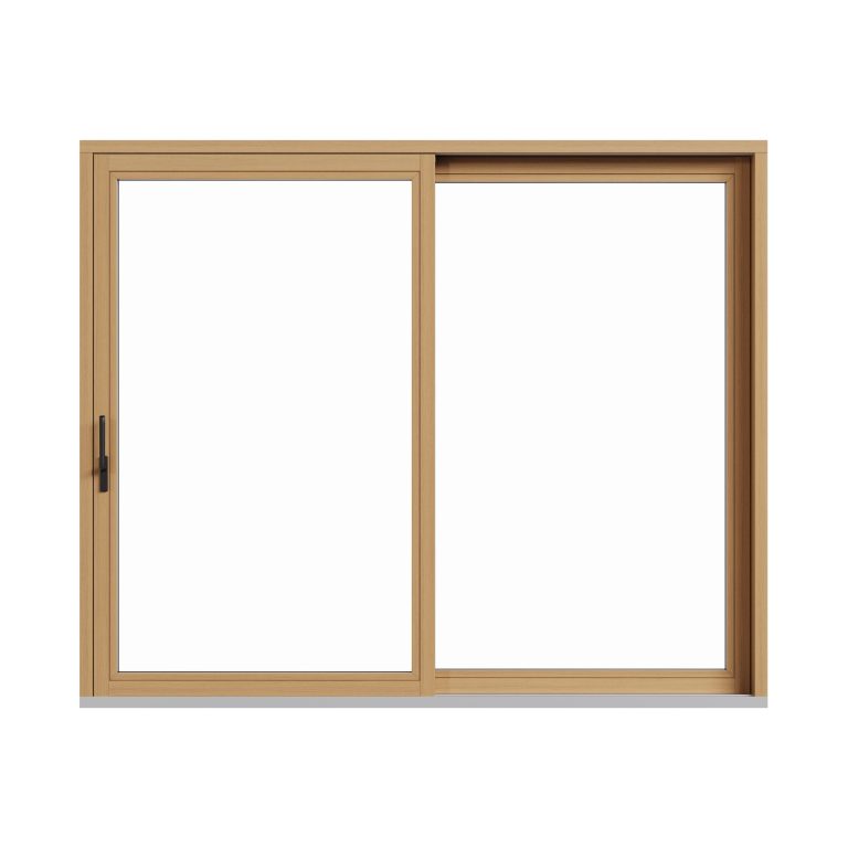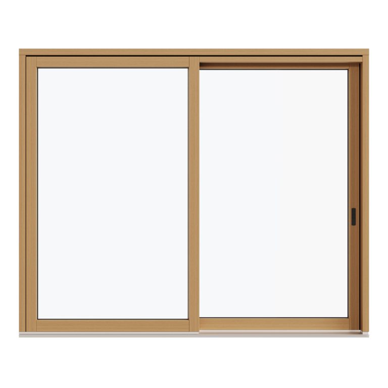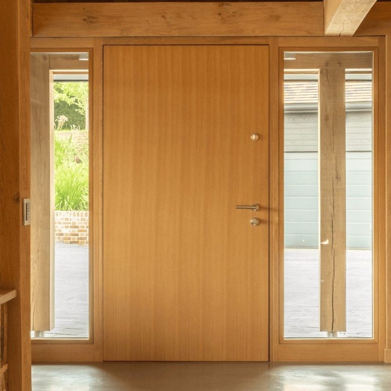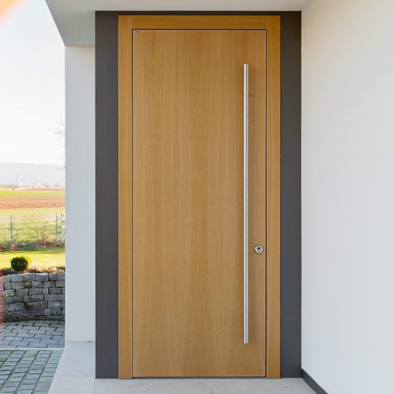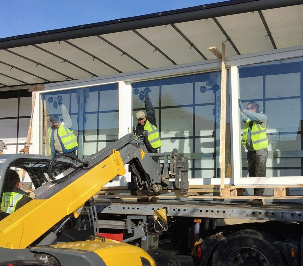
A timber window is installed successfully when the manufactured unit, structural opening and envelope layers work as one assembly. The frame must be square, plumb and level so the sash can move and lock as designed. It must also be sealed, supported and kept dry so its tested thermal, airtight, weather and acoustic performance survives the transfer from factory to wall.
That outcome begins on the architect’s section drawing. Front-to-back position controls the fixing route, reveal geometry, sill projection, insulation overlap, drainage and line of airtightness. The survey then converts the actual opening into manufacturing dimensions. Installation establishes a direct load path through packers, closes the window to wall connection in functional layers and protects the finished timber. A defect at any stage can defeat an excellent product.
Table of Contents
Timber window installation starts with the opening
Positioning the window within the wall build-up
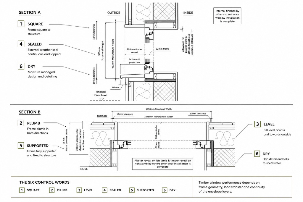
Set the frame position in section before drawing finishes. A frame close to the insulation layer shortens the heat-flow path around the reveal and gives insulation a practical route to overlap the frame. Moving it towards the inner or outer face changes the fixing cantilever, external reveal, solar shading, internal lining and sill depth. It can also expose a colder internal edge if insulation continuity is lost.
The detail must identify the structure that receives load, the air barrier, weather line and drainage route. A dimension to the facade face alone leaves too much unresolved. Give the contractor a datum to the frame or subframe and show how that datum relates to the structural opening.
Designing fixings, seals and sill details
Fixings resist wind, sash operation and unit self-weight; packers transfer compression into the substrate. Seals control rain, air, heat and sound. The sill drains water clear of the face and keeps the timber away from persistent wetting. These are all linked decisions. For example, a projecting frame may need brackets and a deep internal position may need a raised support so the sill can still fall outwards. A flush threshold installation must reconcile level access under Part M with drainage, thermal continuity and bearing capacity.
A finished drawings should show fixing types, fixing zones, potentially packer positions, joint width range, three sealing layers, sill fall, end closures and sequencing with adjacent membranes. Product-specific drawings should always govern installation.
Why installation should be resolved before manufacture
Manufacturing dimensions depend on the largest square opening, the required joint width and the subframe build-up. Late changes to cladding, cavity depth or finished floor level can move the frame away from its designed insulation line or remove the space needed for tapes and other sealing materials. On a large slider, a small threshold-level error can affect the entire opening.
Resolve the chain before release: wall section, frame position, structural support, sealing system, sill or threshold, survey datum, manufacturing size and installation sequence. This reduces site improvisation and gives the main contractor clarity.
Surveying a window opening correctly
Why width and height are not enough
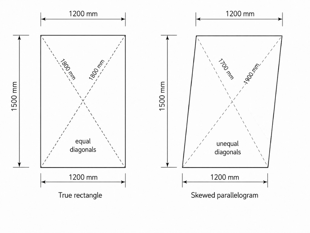
Top and bottom widths can match in a parallelogram. Left and right heights can also match. Those four readings say nothing about diagonal equality, leaning jambs, a sloping head, a sill that rises along its length or twist through the wall depth. A rectangular product ordered from those readings can arrive too large for the square space within the opening.
Establish a horizontal laser datum and a vertical datum. Measure each edge at several points, take diagonals where access permits and record the face at which each reading was taken. Deep openings need front and rear checks because the reveals can be skewed.
Finding the largest square opening
Plot the surveyed edges against the laser datums, then place a square rectangle inside the irregular outline. That inscribed rectangle, with the specified perimeter joint deducted, sets the maximum manufacturing size. Do not average an inward bow and an outward bow. An average can describe a frame that fits nowhere.
Check that packer and fixing zones still land on sound structure. If local high points consume the joint width, agree whether the opening will be corrected before manufacture. Record the accepted structural opening, finished opening and responsibility for remedial work.
Installation tolerances and perimeter gaps
The perimeter gap is working space for levelling, packing, movement, insulation and sealing. Ecovia commonly works with an allowance around 10 mm, adjusted for unit size, substrate, survey variation and the selected sealing system. It is not a universal value required by BS 8213-4.
An installed joint can be 8 mm at one point and 12 mm at another because the frame follows a level datum and the masonry does not. The acceptable range must remain within the tape, foam, membrane and sealant manufacturer’s declared joint limits. A gap that is too narrow prevents full sealing. One that is too wide can exceed movement capacity or leave fixings working across an unsupported void.
Square, plumb and level: the fundamentals of window installation
What happens when a frame is pulled out of square
A fixing screw is powerful enough to pull an inadequately packed timber frame out of square. The factory-made sash remains square, so it then closes into a distorted aperture. Corners contact at different times, gaskets lose uniform compression and locking points no longer meet their keeps on the designed line. Hardware adjustment cannot turn a parallelogram frame back into a rectangle.
Measure diagonals before tightening, after each fixing sequence and at completion. Fixings should retain the packed geometry. They must never be used to drag the frame across a void.
Why plumb matters to heavy opening sashes
The hinge axis of a side-hung sash should be vertical. If it leans, the sash’s centre of mass moves downhill as it swings. Gravity then creates an opening or closing moment, so the sash will not stay where the user leaves it. The effect becomes stronger as sash mass and projection from the hinge line increase.
Check plumb on the hinge jamb in two planes. A single reading on a bowed face is insufficient. Confirm the operation before the joint is concealed.
Correct packing and fixing
Use stable, load-capable packers sized to support the frame without crushing its edge. Interlocking polymer packers permit fine adjustment and limit unnecessary conductive material across the joint. Place them at prescribed fixing points, mullions, hinge zones, locking loads and threshold bearings.
The load path is frame to packer to substrate. A screw clamps and restrains that assembly. It is not a beam carrying the frame across empty space. Packers must not block drainage routes or prevent insulation and seals from forming a continuous line.
Fixing timber windows to different structures
Through-frame fixings
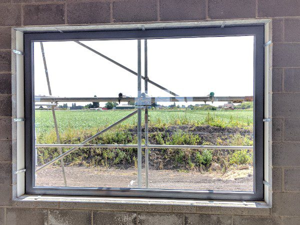
Through-frame fixings provide a direct route into the structure but penetrate the finished joinery. Use manufacturer-approved zones so the fixing does not damage drainage channels, glazing rebates, hardware or aluminium cladding. Drill the timber cleanly with the correct timber bit before drilling the substrate. Recess or countersink the head only where the frame design permits, then finish the opening with an approved plug or repair system.
Tighten against packers. Excess torque can bow a jamb. Confirm diagonal dimensions and sash clearances as the fixing sequence progresses.
Brackets and straps
Brackets or straps can keep the factory finish intact and connect a frame that projects towards the insulation layer. Their design must address cantilever, torsion, fastener pull-out, substrate edge distance and corrosion exposure. Thin straps that look adequate in elevation can be flexible out of plane.
Set bracket centres and fasteners from the product supplier’s installation design and structural loads. Seal any penetration through the air or weather layer. Do not assume a strap removes the need for packers beneath gravity loads.
Masonry, concrete and timber-frame construction
| Substrate | Fixing control | Failure to prevent |
|---|---|---|
| Masonry | Anchor into sound units at verified edge distances; keep bearing behind the frame; avoid relying on weak mortar joints | Split units, loose anchors and a jamb pulled into the cavity |
| Concrete | Select the anchor, embedment and drilling method for the concrete and edge zone; coordinate reinforcement and post-tensioning | Spalling, inadequate embedment or damage to structural reinforcement |
| Timber frame | Fix into designed studs, trimmers or engineered framing; verify any sheathing contribution; reinstate air and weather layers | Fixing into unsupported board, membrane leakage or differential movement |
In every structure, confirm the actual substrate before the unit is lifted into place. Drawings can show blockwork where site openings contain lintel ends, insulation, steelwork or repair mortar.
Fixing heavy doors at hinge locations
A heavy door applies weight and lever action to the hinge jamb. Place solid packing behind the fixing at each designed hinge load zone so the load passes into the structure. Without that bearing, repeated opening cycles can pull the jamb, loosen the fixing or reduce gasket contact at the opposite corner.
Use the door manufacturer’s increased fixing requirement where specified. Check the substrate capacity, fixing length and edge distance. Fine hinge adjustment comes after the jamb has been fixed plumb and fully supported.
Sealing the window-to-wall junction
The interstitial installation gap
The interstitial gap is the space between frame and surrounding construction. It absorbs dimensional tolerance and movement, but it is also a linear part of the envelope. If it remains hollow or receives one discontinuous seal then heat, air, rain and sound can bypass the tested window.
Treat the joint as three functions: external weather resistance, a filled thermal and acoustic zone, then an internal airtight connection. Fire or cavity-barrier duties may add further layers on a project.
Compriband, foam and airtight tapes
Pre-compressed expanding tape, PU foam, full-depth impregnated tape and membrane tape are different products. Compriband expands against the joint faces and can provide movement and weather performance within its declared size range. Foam fills irregular volume and slows heat flow but is not a mechanical fixing or a dependable exposed air barrier. Airtight tapes connect the frame to the building air layer.
Specify the function of each product, joint range, primer, substrate preparation, corner treatment and exposure limit. Expansion speed rises in warm conditions. Keep rolls within the manufacturer’s storage temperature and install only a length that can be positioned before it expands. Prematurely expanded tape may require frame removal and replacement.
Inside airtight, outside weather-resistant
The internal line blocks air movement from the room into the joint. The external line sheds wind-driven rain yet permits the assembly to dry in the direction allowed by the wall design. The middle layer fills the joint without forcing the frame out of shape. The wall build-up determines the required membrane vapour resistance.
At the weather face, lap membranes like roof tiles:
- Install and turn up the bottom piece first.
- Install each side over the ends of the bottom piece.
- Install the top piece over the side pieces.
This sequence directs water onto the layer below. Follow the selected system’s corner pieces, adhesion widths and termination details.
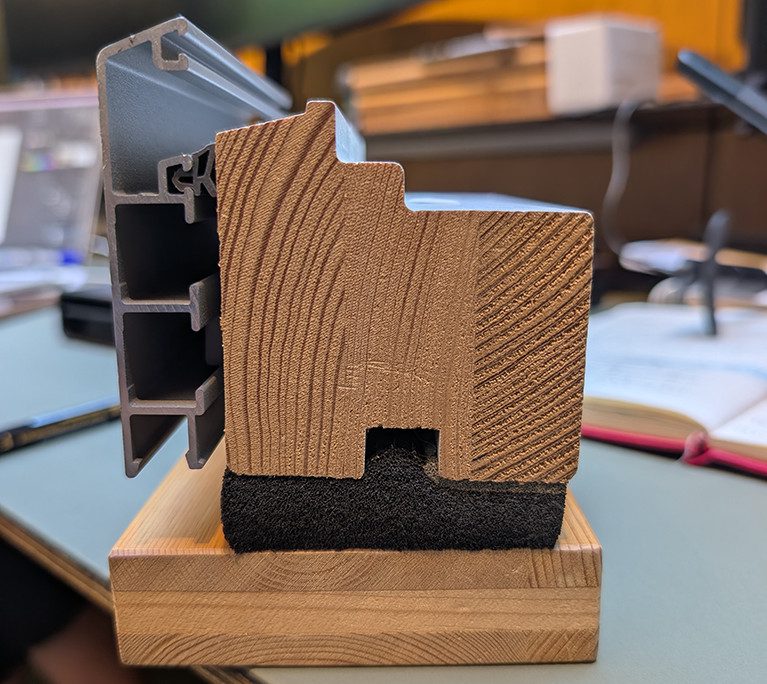
Acoustic installation details
Acoustic performance is continuous from glass to frame, perimeter joint and wall. A high-rated glazing unit cannot compensate for an air path around the jamb. Small open gaps transmit disproportionate sound energy. Deep or dense tapes can improve the joint, but the required build-up must follow tested or assessed project data.
Match joint depth, compression, backing material and seal continuity to the acoustic specification. Check flanking paths through linings, cavities, trickle ventilators and lightweight closures. Do not publish a perimeter dB value without evidence for the complete assembly.
Passivhaus window installation and thermal bridges
Position within the insulation layer
Passivhaus window installation seeks a short, well-insulated heat path around the frame. Position the unit close to the wall’s insulation layer and return insulation over an approved portion of the frame where the system allows. The optimum plane depends on wall type, frame section, fixing system and rain-screen or render build-up.
Model the head, jamb and sill, since the sill and threshold carry loads that can force more conductive materials into the detail. Check internal surface temperature as well as heat loss. A cold edge can create local condensation risk before the whole-window U-value signals a problem.
OSB-box / projecting installation methods
An OSB box or proprietary projecting frame can carry the window out from the main structure towards the insulation. It is one method, not the sole Passivhaus method. The box needs verified member sizes, joints, fasteners, moisture protection and a clear load route back to the wall. OSB grade and exposure class must match the proposed location.
Connect the building air barrier to the box or frame on a stable, continuous surface. Wrap external protection so water cannot collect on horizontal faces. A projecting support that solves heat flow but lacks stiffness can still permit frame movement and seal failure.
Airtightness and installation ψ-values
The installation psi-value, written ψinst and expressed in W/(m·K), represents extra linear heat flow at the frame-to-wall junction. PHPP accounts for this value along the installed perimeter in addition to glass, frame and glazing-edge losses. Each side can differ because head, sill and jamb build-ups differ.
Calculate or obtain assessed values for the actual frame and wall connection. Treat each window installation thermal bridge as a junction-specific calculation. A low ψinst requires insulation continuity and favourable geometry on the drawing, then faithful site construction. Test the airtight layer before linings conceal it. A blower-door result can identify leakage, but it does not prove that structural support or rain detailing is correct.
Sills, subframes and moisture protection
Why under-frame material matters
The material beneath a window or door carries dead load and operational load. It also sits at a high-risk water and heat-flow junction. Timber bearing directly on wet masonry can remain exposed to moisture. A metal packer or continuous metal angle can create a cold route towards the internal threshold. A compressible board can settle and release gasket pressure above.
Specify bearing strength, creep, moisture response, thermal conductivity, fixing capacity and waterproofing as one assembly. Keep point loads aligned with support and protect the timber from wet substrates.
Purenit and thermally improved support
purenit® is a dense recycled polyurethane functional material that can be sawn, drilled and milled with woodworking tools. Its manufacturer declares moisture resistance, dimensional stability, high compressive stress and thermal conductivity far below dense masonry or metal. Those properties make it useful for purenit window installation beneath heavy units and at thermally improved connections.
purenit is not a waterproofing layer and has no blanket approval for every structural use. External work still needs EPDM or another designed weather barrier. The architect and structural engineer must verify section size, bearing, creep, anchors and load for the actual unit.
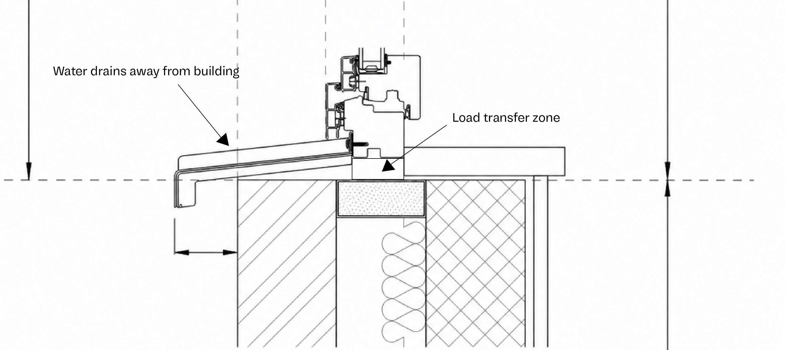
EPDM, sill falls and end caps
Dress the support so any water reaching the sill zone is directed outside. EPDM can form a durable tray or connection membrane if its laps, corners, upstands, adhesion and terminations are resolved. The external sill needs a positive outward fall, adequate projection, a drip and sealed end caps. The project detail should state dimensions based on exposure and the chosen sill system.
Prevent the aluminium sill from making hard contact with external stone or masonry where that contact would bridge insulation or draw water towards the timber. Coordinate the sill with the frame’s drainage outlets.
Preventing rain noise from aluminium sills
A broad unsupported aluminium sill can behave like a musical instrument when rain strikes it. Each drop excites the sheet and the void beneath lets the panel resonate. The noise is then transmitted into the frame and room.
Support the sill as designed and place a resilient EPDM or approved damping layer beneath the sheet. Continuous hard packing can create thermal or drainage problems, so the damping detail must preserve fall, drainage and movement. Confirm the solution with the sill supplier for exposed elevations.
Installing large timber sliding doors
Creating a perfectly level subframe
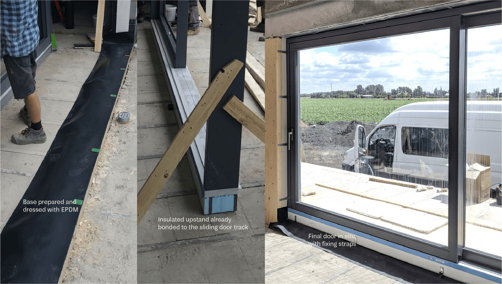
The base of a large slider is an engineered assembly. Ecovia’s site sequence establishes level before the finished track arrives:
- Set out a lower purenit layer to establish the front-to-back position.
- Fix the lower layer to the slab using the designed anchors.
- Place a second purenit layer above it and level this layer independently with stable packers against a laser datum.
- Check the full length at close intervals, including both front and rear bearing lines.
- Fix the two layers together without disturbing the levelled plane.
- Dress the assembly with EPDM, forming corners, upstands and external drainage.
- Recheck level and twist after waterproofing.
- Place the sliding door on the pre-levelled base, then fix and brace it to the approved points.
Do the levelling in the subframe. Ad-hoc packers placed under isolated points of the finished running track can bend or twist the track between supports.
Why a laser is essential
A long spirit level reports the relationship between the points it touches. It can bridge a local hollow or high point between them. A rotating or line laser establishes one datum across the entire opening, allowing the installer to compare many support points without moving the reference.
Record readings before placing the unit and after fixing. The latter check detects movement caused by anchor tightening or bedding compression. Protect the laser datum from being reset partway through the work.
Preventing track twist
Level along the length is only one axis. The front and rear edges of the track must also share a plane. If one edge rises, the roller assemblies run on a twisted rail. The sash may move freely in one zone and bind in another.
Use laser checks across both bearing lines. A tensioned string between the ends gives a direct check for local deviation along the rail; repeat it at the front and rear. Do not pull the frame into alignment with fixings after the track has been loaded.
Allowing for structural deflection above the door
Steel, glulam and timber box beams can deflect over a long opening. If rigid packers or hard foam create a load path into the door head, the frame becomes an unintended prop. Head movement can squeeze the track geometry, load the glass and stop the locking system.
The structural engineer must state expected short-term and long-term movement. Coordinate a product-approved head allowance and fixing arrangement. A compressible mineral-wool layer may close the thermal and acoustic void without carrying structural load, subject to the fire, air and weather design.
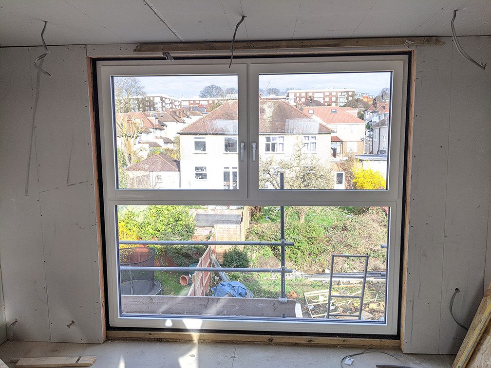
Protecting timber windows after installation
Why timber should not simply be shrink-wrapped
Tight polythene can trap water vapour or liquid against a coated timber surface. Solar heating then creates a warm, humid pocket with little drying. Staining, discolouration and coating damage can follow. Factory-applied coatings slow moisture exchange but do not turn timber into an impermeable material.
Protection must stop impact and dirt without sealing damp joinery inside a plastic bag. Follow the window and coating supplier’s site-care instructions.
Physical site protection
Use freestanding or lightly fixed Correx guards, OSB barriers and temporary rails in traffic zones. Protect sills from tools and foot loading. Shield exposed corners from plasterboard, scaffold tubes and material handling. Keep ventilation paths around the joinery and leave drainage openings clear.
Do not attach aggressive tape to the finished coating unless the supplier approves it. Mark protected openings so following trades do not remove packers, braces or seals.
Cleaning and safeguarding finished surfaces
Remove wet plaster, mortar, concrete slurry and standing water before they cure or soak into joints. Use pH-neutral cleaners and soft tools approved for the coating and glass. Blades can scratch coated glass or timber finishes. Metal swarf left on an aluminium-clad surface can rust and stain it.
Inspect protection after each wet trade and after scaffold changes. Record damage before handover so responsibility and repair method are clear.
Construction moisture: the overlooked risk after installation
Wet trades release far more water than the completed building is designed to manage as an occupied space. Screed, plaster, render and concrete dry by transferring moisture into the air. Once windows are installed and the air barrier is closed, uncontrolled infiltration drops and that water remains within the building until ventilation or dehumidification removes it.
Timber is hygroscopic. Its moisture content moves towards equilibrium with the surrounding air. Its dimensions change as moisture is gained or lost. Engineered lamination and factory coating reduce distortion and slow exchange. They do not remove the material response. The construction moisture to which timber windows are exposed is a programme and building-services issue, not a joinery defect by default.
Screed, plaster and wet trades
The main contractor should estimate when major wet loads enter each zone and plan drying before closing rooms. Plastering beside a finished frame can wet the coating, seals and porous substrates. Screed can release moisture for weeks, with the rate controlled by mix, depth, temperature, air movement and floor finish programme.
Keep wet material and wash water off frames. Open internal doors to support planned air movement, but do not spread moisture into dry zones without an extraction route. Log trade dates and environmental readings so a later operational issue can be assessed against evidence.
Why timber can swell on an excessively humid site
Water molecules bind within the timber cell walls as surrounding humidity rises. The section expands across the grain, reducing the clearance between sash and frame. Paint, hinges and gaskets cannot create extra clearance. If the moisture load continues, locking points can bind and a sash can become difficult to open.
Species, lamination, section, coating and exposure affect the amount and rate of movement. Measure timber moisture content with a calibrated meter at agreed locations if abnormal conditions are suspected. Compare readings with supplier instructions and baseline records without applying an unverified universal limit.
Dehumidifiers and controlled drying
A drying plan needs monitored relative humidity, controlled ventilation, suitable heat and dehumidification where readings or trade loads demand it. Heating accelerates evaporation but does not remove water from a closed building. The moisture must leave through extraction, purge ventilation or collected condensate.
Size and select dehumidifiers for air volume, temperature and water load. Drain condensate safely and keep units running through the required cycle. Protect permanent MVHR equipment from construction dust and do not treat it as a site dryer without approval from the MEP designer and manufacturer. Use data loggers to verify trends instead of relying on a brief handheld reading.
Temporary jamming and glazing-bead movement
When swollen timber consumes the designed clearance, forcing the sash can damage hinges, locking cams, gaskets or the finish. Sanding the sash or permanently shifting the hardware can create excessive gaps after the building dries. Isolate the opening if needed, record conditions, dry the zone and reassess geometry once moisture content normalises.
Moisture movement can also open fine lines at glazing-bead mitres. The product may move back towards its delivered dimensions as conditions stabilise, but coating or local finishing work can still be needed. Obtain the supplier’s repair method before cutting, filling or repainting.
Why airtight modern buildings need particular attention
High airtightness removes the incidental air leakage that once carried part of a wet trade’s moisture away. This is beneficial in service and demanding during construction. A sealed house can hold a large vapour load even when permanent ventilation terminals are present but not commissioned.
Assign responsibility for environmental monitoring, plant operation and response thresholds. Coordinate the dry-out programme with air tests, floor finishes, decorating and joinery handover. Permanent Part F ventilation supports occupied indoor air quality; construction drying is a separate temporary duty.
Final inspection, adjustment and handover
Glass and finish inspection
Inspect glass under the supplier’s stated viewing method and lighting conditions. Check timber coatings, aluminium cladding, beads, corners, sealant edges and protective-film removal. Confirm drainage slots are open and sill end caps are complete. Photograph finished junctions before trims hide them.
Separate manufacturing defects, installation damage and following-trade damage in the record. Use approved local repair systems so a cosmetic correction does not compromise coating warranty.
Operational checks
Operate every sash and door through its full travel. Check stay positions, restrictors, locking points, handles and safe clearances. A sash should not self-open or self-close because the hinge axis is out of plumb. A slider should move consistently along the whole track without a rising effort that signals slope or twist.
Repeat checks after adjacent finishes and threshold floor layers are complete. Debris in a track can mimic a geometry fault.
Gasket compression and hardware adjustment
Use paper-pull or supplier-approved checks around the gasket line to identify uneven compression. Eccentric locking cams can tune pressure, but adjustment cannot repair a distorted frame or unsupported hinge jamb. New gaskets can make operation firmer until they bed in.
Make final hardware changes after fixings, seals and finishes are complete and site moisture is controlled. Record the settings and do not use adjustment to conceal movement that still requires diagnosis.
Client/site-team moisture instructions
Handover begins with the main contractor before it reaches the occupant. Name the person responsible for monitoring conditions and provide the joinery supplier’s storage, protection, cleaning and moisture instructions. State the reporting route for stiff operation or swelling. Early evidence allows the team to separate temporary moisture movement from geometry, debris or hardware faults.
Site handover checklist
- Monitor internal relative humidity and record trends by zone.
- Measure timber moisture content where the supplier or abnormal conditions require it.
- Use controlled ventilation and dehumidification as screed and plaster dry.
- Provide suitable temporary heat as part of the drying design, with a route for moisture to leave.
- Do not wrap timber airtight in polythene or seal damp joinery behind impermeable protection.
- Keep wet plaster, screed, wash water and standing water off frames and thresholds.
- Keep drainage slots, sill falls and ventilation paths clear.
- Record site conditions and photographs if swelling or stiff operation occurs.
- Do not force swollen sashes.
- Do not sand timber or permanently alter hardware to compensate for temporary moisture movement.
- Reassess operation after environmental conditions and timber moisture content have stabilised.
- Complete final adjustment, cleaning and sign-off at the end of the dry-out period.
High-performance glazing is a system that runs from wall design through survey, manufacture, fixing, sealing, threshold construction, protection and controlled drying. The factory values reach the completed building only when every link in that chain is designed, inspected and handed over.
Timber window installation: brief overview
Set the unit square, plumb and level on a verified structural support, mechanically fix it to the correct substrate, seal the perimeter in weather, insulation and airtight layers, then protect and monitor the timber through construction drying.
Tools: Laser level, calibrated tape, diagonal measuring equipment, drill and bits matched to timber and substrate, torque-controlled driver, moisture meter where required and approved cleaning tools.
Materials: Project-designed fixings, stable packers, specified compriband or foam, airtight and weather membranes, primers, EPDM, sill components and a verified thermally improved support where detailed.
Steps:
- Resolve the wall position, support, fixings, sealing layers and sill or threshold before manufacture.
- Survey the opening against horizontal and vertical laser datums and establish the largest square opening.
- Confirm manufacturing size and joint width against the selected sealing system.
- Build and verify the support or subframe, including level, bearing, waterproofing and thermal continuity.
- Place the frame, pack all load points and prove square, plumb and level.
- Fix to the designed substrate without pulling the frame away from its packed geometry.
- Form the external weather layer, filled middle joint and internal airtight layer in the specified sequence.
- Complete sills, end caps, drainage and any Part M threshold coordination.
- Protect the finish without trapping moisture, then run the construction-drying plan through wet trades.
- Inspect glass and finishes, test operation, set gasket compression, record conditions and hand over moisture instructions.
FAQs about timber window installation
How should timber windows be installed?
Set the frame on verified bearing, pack it at load and fixing points, prove it square, plumb and level, then fix it to sound structure. Complete an external weather seal, insulated middle joint and internal airtight seal. Protect the timber and control construction moisture before final adjustment.
What does square, plumb and level mean when installing windows?
Square means the frame corners and diagonals form a true rectangle. Plumb means the jambs and hinge axis are vertical. Level means the sill and head follow a horizontal datum. All three are required for even gasket contact, reliable locking and predictable sash movement.
How much installation gap should there be around a window?
There is no universal gap for every product and opening. Ecovia commonly works around 10 mm, but the specified range must account for survey variation, unit size, movement, packers and the declared limits of the foam, tape, membrane and sealant system.
Why do windows need packers?
Packers transfer compression from the frame into the substrate and hold the designed geometry as fixings are tightened. Without a packer, the screw spans a void and can pull the timber out of square or bow a jamb. Heavy hinge and threshold loads need direct bearing.
Should windows be fitted with expanding foam or compriband?
Choose by function. Foam fills irregular space and limits heat flow. Compriband expands against joint faces and can provide movement or weather performance within its rated range. Airtight membranes form the internal air seal. One product should not be assumed to perform every task unless the tested system says it does.
How do you make a window installation airtight?
Connect a continuous internal tape or membrane from the frame to the building air barrier. Prepare and prime substrates, form sealed corners and close penetrations. Test before linings hide the work. Foam in the middle of the joint does not by itself prove airtightness.
How are Passivhaus windows installed?
The frame is placed near the insulation layer, structurally fixed through an assessed support and connected continuously to the air barrier. Insulation returns towards the frame and the head, jamb and sill are checked for ψinst and internal surface temperature. An OSB box is one available method.
What is an installation ψ-value?
ψinst is the linear thermal transmittance of the installed frame-to-wall junction in W/(m·K). Multiplied by junction length, it adds the heat flow created at the head, jambs and sill to the window and wall calculations. It depends on the actual geometry and materials.
How do you install a timber window without creating thermal bridges?
Place the frame close to the insulation plane, overlap it with compatible insulation, reduce conductive supports and keep the perimeter fill continuous. Model critical junctions. Structural support cannot be removed to improve a calculation, so use a load-capable thermally improved support where the design requires one.
Why must sliding-door tracks be perfectly level?
A heavy sash on a rising track makes the user push hundreds of kilograms uphill. Twist places the front and rear roller paths on different planes, causing local binding. Establish the support against one laser datum before the door arrives and verify both bearing lines.
What should sit underneath a sliding door?
Use a project-designed base that carries the unit into the slab or structure, remains level under load, limits heat flow and can be waterproofed. Ecovia uses engineered purenit build-ups on suitable projects. Section size, anchors, packers and bearing must be verified for the actual door.
How do you prevent water getting underneath timber windows?
Provide an external weather membrane or EPDM tray with sealed corners and upstands, then direct it to a sill with positive fall, end caps, projection and a drip. Keep frame drainage outlets open and prevent hard sill contacts from drawing water towards the timber.
Can newly installed timber windows swell?
Yes. Timber takes up moisture in an excessively humid building and expands across the grain. Engineered sections and coatings reduce the response but do not remove it. Measure conditions, control drying and let the supplier assess the product before permanent changes are made.
Why are new timber windows difficult to open after plastering?
Construction humidity is one possible cause because wet plaster and screed release water into the air. Swollen timber can consume the opening clearance. Debris, frame distortion or hardware faults can produce similar symptoms, so record moisture and geometry before diagnosing or adjusting.
Should dehumidifiers be used after installing timber windows?
Use them when the construction-drying design and monitored conditions call for active moisture removal. Select capacity for the zone, temperature and wet-trade load. Provide safe condensate drainage and data logging. A heater in a sealed room can evaporate water without removing it.
What humidity should a construction site be kept at after timber windows are installed?
Use the window, timber and coating supplier’s verified site range and record it in the project handover information. Ecovia should not publish one generic RH limit across every species, finish, season and building. Monitor trends and timber moisture content where required.
Can you cover timber windows in plastic during building work?
Do not seal them tightly in polythene unless the product supplier provides a specific method. Impermeable wrapping can trap moisture against the coating. Use ventilated impact protection, keep water away and leave drainage routes clear.
When should new windows receive their final adjustment?
Adjust them after structural fixings, seals, adjacent finishes and cleaning are complete and after abnormal construction moisture has been controlled. Earlier checks are still required, but permanent hardware changes should not compensate for a wet frame or an installation that is out of square.